Zero Delay Wiring Diagram
For example, the shipping method can be negotiated freely and the sample is provided in the hope of gaining comments. But we are sure of our services provided from blee arcade parts can differentiate ourselves.
Zero Delay Usb Encoder Wiring Diagram LIFEOFMISSLIPS
A great solution to attain that retro feeling!
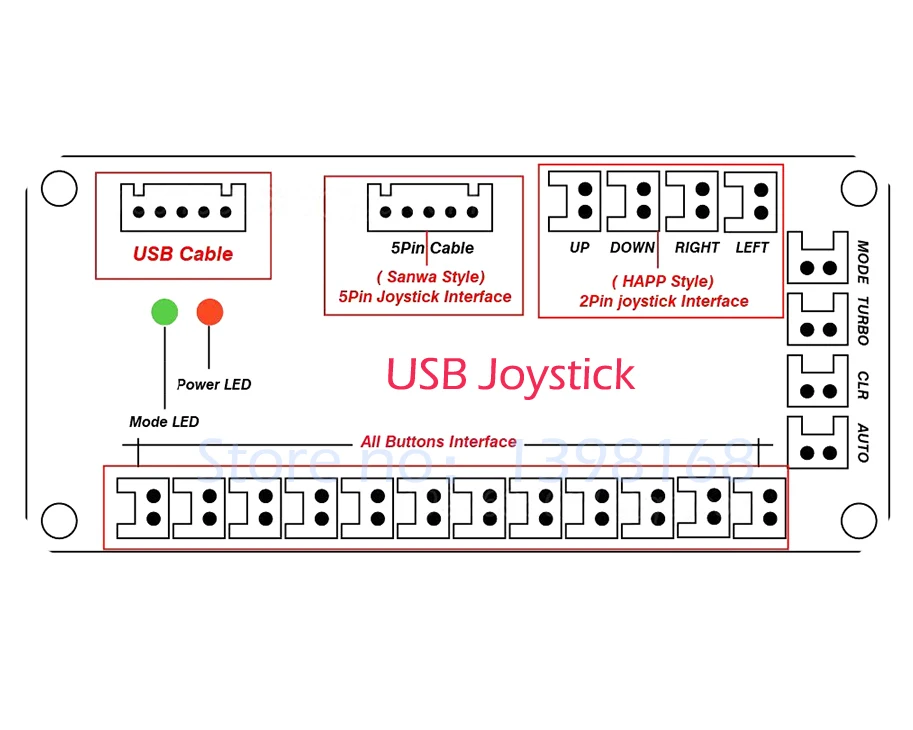
Zero delay wiring diagram. We are going to wire up the joystick first, so grab that and the ribbon cable. Plug one end of the ribbon cable into the joystick port, then plug the other end onto the 5 pins on the joystick. The above switching arrangement will.
Zero delay usb joystick encoder s config Is2000z wire harness 5401327 nc no com 85 86 30 87a 87 relay 5021766 nc nc lh neutral switch 5021451 no 85 86 30 87a 87 relay 5021766 auxilary connector black green blue blue orange orange/white orange/green orange/white orange orange/green yellow yellow yellow orange white white black black white gray gray black black orange orange time delay. Zero delay usb encoder true analog joystick modification.:
You need to have successfully modified, tested and calibrated the encoder in the previous project before adding this device. Zero delay usb encoder wiring diagram this is an additional project to the zero delay usb encoder true analog joystick modification. Zero delay arcade usb encoder wiring diagram we well know that zero delay arcade usb encoder wiring diagram competes in the fierce market.
Trigger pin is dragged from the negative input of comparator two.the comparator two output is connected to set pin of. Timing diagram icm254 post purge timers ctvs on delay/off delay controls circulating fan in hvacr system wiring diagram control transformer line voltage fan t'stat c r g 7313 william barry blvd. Zero delay usb encoder wiring diagram.
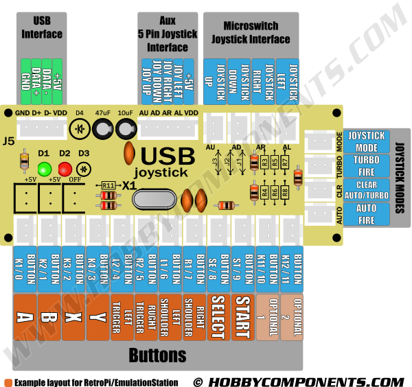
The arcade controls wiring wouldn't be complete without connecting everything to the encoder board. The statement b = 1 will be executed at time 10 and others at time 30,35 and 45. Button diagram arcade controls wiring:
The two pin / two 0.110 quick disconnect wires connect to the microswitch tabs. Color coded wiring diagram for bobcat zero turn delay module 2188154. The delay turns off the load and resets the time delay to zero.
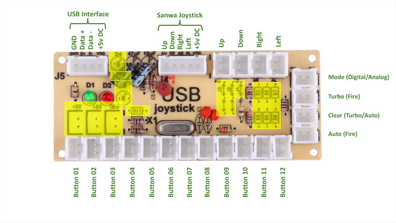
During the delay on make period, the delay on make period is reset to zero. Zero delay usb encoder wiring diagram. Start by getting the usb encoder pcb board and take note of the connections.
The cable may be used to transfer information from 1. Enter the zero delay usb joystick encoder. New zero delay usb encoder wiring diagram background.so you've just received your zero delay arcade usb encoder and its time to wire it up!
When completed and working it… This pin should be connected to ground. Zero delay board arcade usb encoder to pc raspberry pi zippy joystick control sanwa american push button connection cable arcade usb encoder pc zero delay arcadezippy joystick aliexpress.
This entry isn't as much of a tutorial but an over view of a device that has been selling on the net known as a zero delay usb joystick encoder. it goes by other names such as a a diy arcade replacement c Us 10 26 5 off zero delay usb encoder to pc games for arcade sanwa joystick buttons kits parts use on 5 pin roker and 2 8mm buttons interface in. This zero delay comes with standard 187 and 250 wiring that will both power and illuminated your arcade push buttons.
These timed contacts are in series with motor starter m2. So you've just received your zero delay arcade usb encoder and its time to wire it up! I 2 bo 0 ed a x b x.
Beranda zero delay arcade usb encoder wiring diagram zero delay usb encoder wiring diagram. Before going into detail of time delay circuit, first we need to learn about 555 timer ic first.below you can find the pin diagram of 555 timer ic along with the details of each pin. So youve just received your zero delay arcade usb encoder and its time to wire it up.
In the below code, execution of line 11 to 14 statements are controlled by some delays. Wiring & mounting wiring diagram ceiling mounting controls & settings product controls dip switch settings X arcade wiring diagram jamma to usb wiring diagram usb.
North syracuse, ny 13212 icm controls 800.365.5525 www.icmcontrols.com. Part 2 takes a closer look at the zero delay usb interface pcb itself Zero delay usb to joystick controller with cheap price.
They are wired in series between the +5v and zero volts pin of the usb connection from the pc. We have the modules you need, with fast shipping. In this section, we will cover the basics of this board, its pinout, and wiring diagrams.
Wiring a happ joystick to a zero delay encoder. This is an additional project to the zero delay usb encoder true analog joystick modification. See the related products tab below.
Wiring diagram control transformer line voltage fan t'stat c r g 7313 william barry blvd.

Zero Delay Usb Arcade Encoder Review & Playtest

SJJX Arcade USB Encoder LED Zero Delay Arcade Controller
Usb Encoder Wiring Diagram USB Wiring Diagram


SJJX Arcade USB Encoder LED Zero Delay Arcade Controller

SJJX Arcade USB Encoder LED Zero Delay Arcade Controller

SJJX Arcade USB Encoder LED Zero Delay Arcade Controller

RetroPie Raspberry Pi Minicade (UPDATE 2) Matt's Shack

JOYiT Zero Delay Encoder USB Joystick Elektor

Zero Delay Usb Encoder Wiring Diagram LIFEOFMISSLIPS

Individual Zero Delay Wires 0.110" Retro Active Arcade
Placa zero Delay+cabo com terminais Arduino e Eletrônica

Usb Joystick X1 Wiring Diagram USB Wiring Diagram

Top 10 Best Sjjx Zero Delay Reviewed And Rated In 2022
Usb Control Board Wiring Diagram Complete Wiring Schemas

Zero Delay Usb Encoder Wiring Diagram LIFEOFMISSLIPS

Zero Delay USB Arcade Encoder .187" Wiring Retro Active

Usb Encoder Wiring Diagram USB Wiring Diagram

Top 10 Best Sjjx Zero Delay Reviewed And Rated In 2022

2 Player Zippyy Zero Delay MAME Arcade Bundle Retro


